
Automotive CNC Machining
Automotive parts iterate faster than anything else on this site. A bracket goes through three design revisions in the time an aerospace fitting goes through one, and the cost-saving conversation is rarely "which alloy is cheapest" — it's "which prototype method matches this stage of the program". Pick the wrong one and you have a beautifully-machined part that should have been a 3D-printed fit-check, or a vacuum-cast lookalike sitting on a dyno where a real machined billet was needed.
For OEM, EV, and motorsport programs, we run the full prototype lifecycle: concept fit-check parts through engineering validation, production validation, and bridge production runs that fill the gap before high-volume tooling is ready. The quote tells you which method we recommend for each line on the BOM and why.
What we handle
- Powertrain, driveline, brake, suspension, EV battery, motor housing, and motorsport components on prototype, bridge, and pre-tooling production runs.
- Aluminum (6061, 6063, 7075), steels (1018, 4140, 8620), brass, cast aluminum, and engineering plastics — sourced against your drawing's grade and condition.
- IATF 16949-controlled quality system for automotive programs that need PPAP-style supplier qualification.
Why automotive prototypes need a method conversation, not just a quote
An automotive RFQ that lands here without a stage callout is missing the most expensive piece of information in the conversation. A part headed for a concept review meeting next Tuesday and a part headed for an EV battery enclosure that needs to survive vibration testing at supplier validation are not the same job — even if the CAD model is identical. The first one wants a fast 3D print or a low-cost cast urethane copy. The second one wants billet aluminum cut to drawing tolerance because the dyno is going to find every shortcut.
The matrix below is the short version of how we steer that conversation. It is not a price list; it is a method-selection map that tells you which prototyping route fits which validation milestone. Use it during early design to rule routes in or out before the BOM locks, and the resulting quote comes back with a method per line item rather than a one-size-fits-all "we'll machine it" answer.
Prototype lifecycle vs method choice
Six common stages, four method options, one decision per line on the BOM. Use the table to match the prototyping route to the validation milestone before quoting — it saves a quote round-trip and usually saves real cost on the program.
| Program stage | 3D printing (SLA / SLS) | CNC machining (billet) | Vacuum casting (urethane) | Hard tooling |
|---|---|---|---|---|
| Concept fit-check | Best — fastest, cheapest, finish doesn't matter | Overkill | Overkill | Wrong stage |
| Functional prototype (low load) | Acceptable for non-load parts | Best — tested in real material | Good for cosmetic and visualization | Wrong stage |
| Engineering validation (test cell) | Inadequate for real load cases | Best — billet matches the production-intent material | Limited — urethane parts won't survive dyno or thermal cycles | Premature |
| Production validation | Not appropriate | Best — drawing-controlled production-equivalent parts | Limited use | Premature unless volume justifies it |
| Bridge production (10–500 units) | Not cost-effective | Best — same parts as PPAP, no tooling lead time | Cost-effective for cosmetic and trim parts | Tooling lead time may not justify it |
| Pre-tooling production (500+ units) | Not appropriate | Cost-effective up to a crossover point | Cost-effective for cast-suitable geometries | Best when volume justifies the tooling investment |
Two practical patterns turn up most often: a part starts on 3D printing for fit-check, moves to CNC billet for engineering and production validation, and either stays on CNC for bridge production or moves to hard tooling at the volume crossover. Vacuum casting fills the cosmetic-and-trim niche for low-volume runs where tooling cannot be justified.
From fit-check print to production-ready anodize
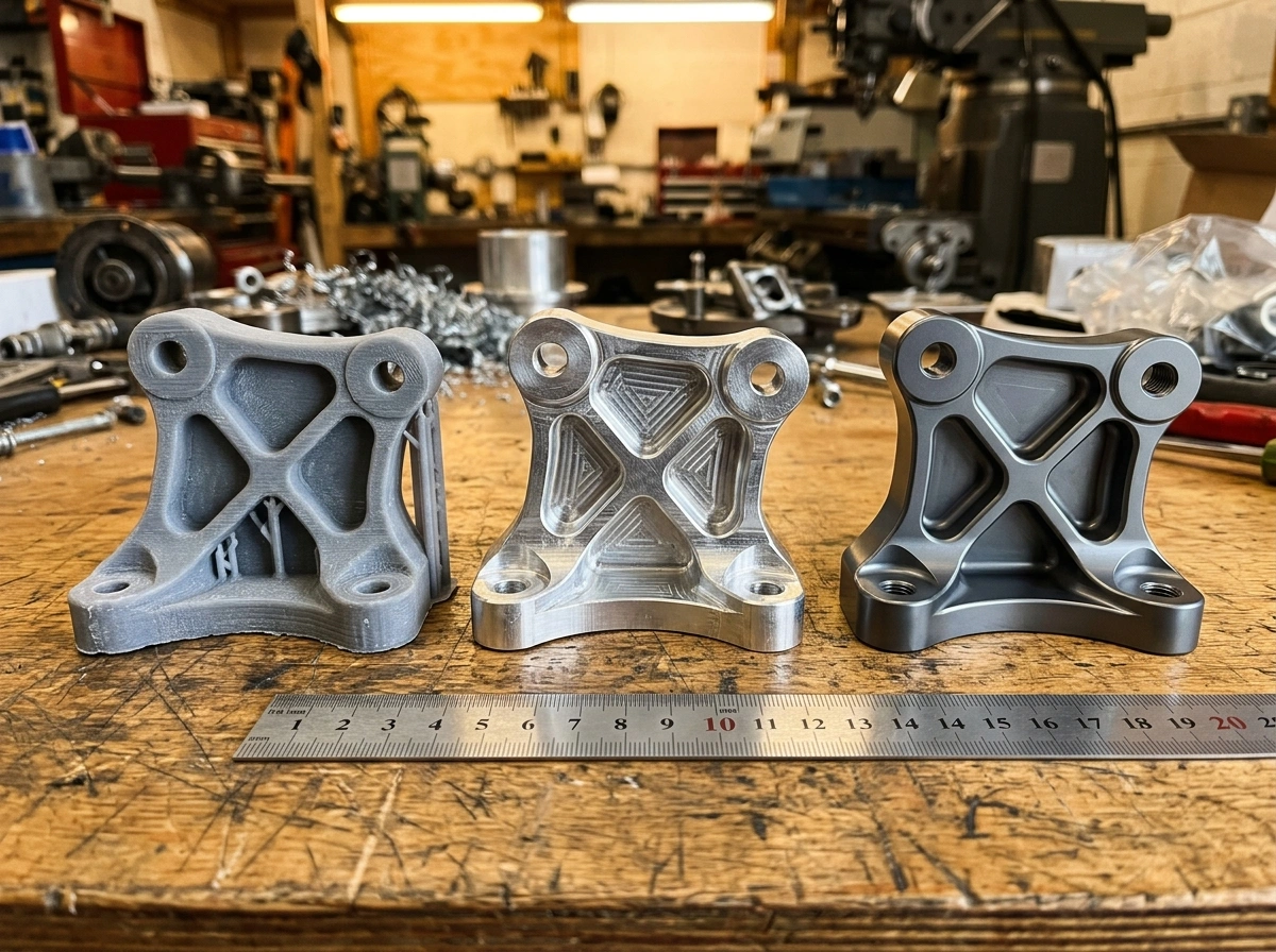
The same bracket on three milestones looks different on each. A 3D print answers the concept fit-check question — fastest and cheapest when finish and material do not matter. A CNC billet answers the engineering and production validation questions, because the test cell and the dyno find every shortcut a lookalike prototype tried to hide. A finished production part — anodized or chemical-conversion-coated per the assembly drawing — proves the supply chain can repeat it through bridge production and past the volume crossover to hard tooling without silent drift.
Two patterns turn up most often on automotive programs. A part starts on 3D printing for concept review, moves to CNC billet for engineering and production validation, and either stays on CNC through bridge production (10–500 units) or hands off to hard tooling once volume justifies the tooling investment. The other pattern fills the cosmetic and trim niche: vacuum-cast urethane copies cover low-volume runs where injection tooling cannot be justified and where the load case does not need billet aluminum. Method per line item is the point — not a one-size-fits-all "we'll machine it" answer that leaves cost and schedule on the table.
Automotive programs here run under an IATF 16949-controlled quality system where the BOM calls for PPAP-style supplier qualification. Material choice follows the lifecycle: 6061 and 6063 aluminum for EV battery housings, motor end caps, and most prototype work; 7075 where the load case demands it; 4140 or 8620 steels where hardening matters; cast aluminum (A356, A380) where finish-machining supplied castings is on the routing. We flag the crossover point where tooling replaces billet, so the handoff lands on the engineering calendar rather than at the end of a frustrated phone call.
Fuel cell components we machine
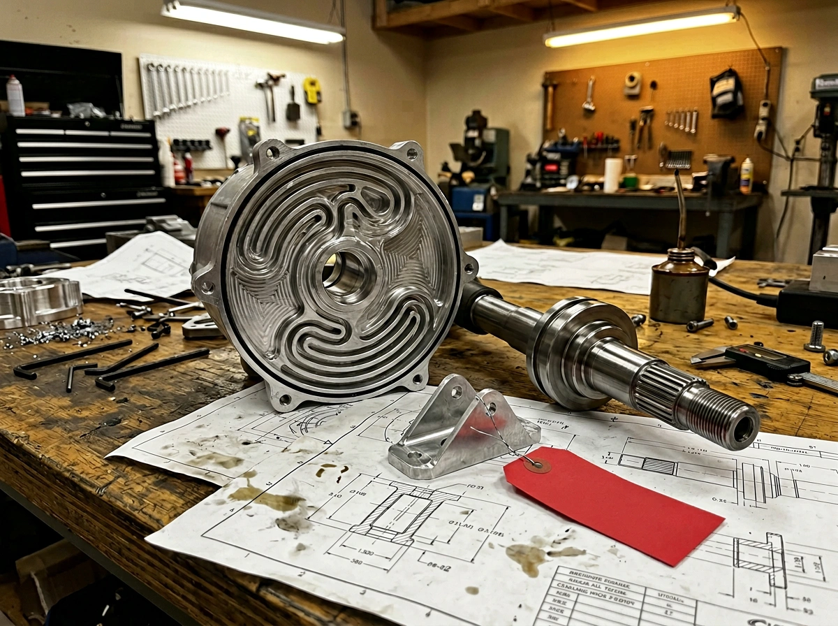
We machine fuel cell stack hardware in aluminium and stainless—end plates, manifolds and port plates, coolant and cooling plates, sealing faces, and metallic bipolar plates. This is not a harder version of a bracket. It is a set of large, thin, flat parts whose function lives on their sealing surfaces, which makes distortion, fixturing, and flatness verification the entire conversation, and makes material a corrosion decision before it is a machining one. What follows is how we plan each one, and what we need on your drawing to quote it.
| Component | What drives the machining plan | What has to be on the drawing |
|---|---|---|
| Bipolar plates (metallic) | Thin section over a large area, so clamping and cutting forces both distort the part. Flow-channel depth consistency matters more than any single dimension, and the plate has to stay flat after it comes off the fixture, not merely while it is on it | Flatness over the sealed area with its datum scheme; channel depth tolerance; surface condition in the contact region; whether flatness is verified free-state or constrained. We machine these in stainless and aluminium—send the material specification with the RFQ if your design calls for graphite or a coated substrate, so we confirm the route before quoting |
| End plates and compression hardware | Stiffness is the point—these carry the stack compression load. Bolt-pattern position and parallelism between the two loaded faces determine whether the stack seals evenly | Parallelism between loaded faces, positional tolerance on the bolt pattern, and the assembly torque the design assumes |
| Manifolds and port plates | Cross-drilled intersections, internal burrs that no inspection sees, and sealing faces around every port. Deburring internal intersections is real, quotable work | Internal cleanliness and deburr requirement; port sealing-face finish; whether pressure or leak testing is in scope and to what standard |
| Coolant channels and cooling plates | Passage geometry against machinability: features reachable by a cutter, or a plate that has to be machined in two halves and joined. That decision belongs in design, not in quoting | Passage cross-section and minimum internal radii; joint method if the plate is split; leak-test pressure and acceptance criterion |
| Sealing surfaces and gasket grooves | Groove width, depth, and corner radius against the gasket the design assumes. Surface finish in the groove is a sealing requirement, not a cosmetic one | Gasket part number or cross-section, groove tolerances, and the surface finish callout with its measurement direction |
| Material and corrosion | The stack environment is humid and acidic, so the material and any coating are corrosion decisions. Stainless grades and coated substrates behave very differently under the cutter and in service | Grade and condition, any coating specification, and the contact-resistance or conductivity requirement if the part carries current |
The common thread is that almost none of these parts are defined by a single tight dimension. They are defined by form across a large surface, by what happens after the part is unclamped, and by what the sealing face has to do. An RFQ that sends the model and the flatness scheme together gets a useful quote; one that sends the model alone gets questions.
Flatness and parallelism on stack hardware are verified on our own coordinate measuring machines, and we will agree free-state versus constrained measurement with you before the first plate runs rather than after a lot is rejected. Where a fuel cell program needs prototype plates before the design locks, the same method-selection logic from the table above applies—see rapid prototyping, and CNC milling for the underlying process.
Thermal management and EV power electronics hardware
Everything that moves heat in an electrified vehicle is a machined part with an internal passage and a sealing face. Everything that moves current is a machined part with a flatness and a finish requirement. Both categories fail in the same two places: the joint and the burr.
Cold plates and cooling plates
Passage geometry is a manufacturability decision made in CAD. A serpentine channel a cutter can reach is one part; a passage that forces a split plate and a joining operation is a different part with a different cost and a leak path. Ask the question before the design locks, not after.
Coolant galleries and cross-drilling
Drilled intersections leave burrs where nothing can see them and everything can feel them. Internal deburring on a gallery is quotable work with a defined method—specify it, because “deburred” means something different to every shop that reads it.
Heat exchanger bodies
Large aluminium parts with thin webs and a lot of material removed. Residual stress in the stock is the usual cause of a part that measured well on the machine and was out of flat by the time it reached inspection—stress relief between roughing and finishing is the fix, and it belongs in the routing.
Busbars and current-carrying parts
C110 ETP copper is soft and smears; burr control and edge condition drive the tooling choice rather than cycle time. Contact faces need a flatness and finish callout, and if plating follows machining, the plating consumes dimensional budget that has to be planned in.
Inverter and converter housings
Aluminium housings that have to seal, conduct heat out, and locate a PCB stack. Sealing-surface flatness, bore positional tolerance, and thread condition are the features that matter; the outside profile usually is not. Say which is which on the drawing.
EMI shielding and sealing features
Shielding gaskets and conductive seals need a defined groove and a defined contact surface—including whether that surface can be anodized at all, since a hard anodic coating is an insulator. That conflict is best found on the drawing rather than at assembly.
One point worth making early on any electrified program: a conductive contact face and an anodized face are mutually exclusive. If a housing needs both corrosion protection and an electrical bond path, the bond area has to be masked, and masking is a quoted operation with its own tolerance. See surface finishing, and the specification table below.
Automotive part categories we machine
Six categories cover the bulk of automotive work that lands here. Yours probably matches one of them or sits between two — describe the function and we can usually peg the right pattern from a one-paragraph brief.
Powertrain & engine components
Cylinder heads, manifolds, intake and exhaust hardware, oil pump and water pump bodies, valve covers. Usually cast aluminum stock for high-volume production parts; billet 6061 or 7075 for prototype and motorsport runs where the geometry hasn't locked yet.
Driveline & suspension hardware
Hubs, knuckles, bearing carriers, spindles, control arm fittings, custom mounts. Steel grades (4140, 8620) where strength and case hardening matter; aluminum where mass reduction is the program target.
EV battery & motor housings
Battery pack enclosures, cell holders, busbar hardware, motor end caps, charging port components. Aluminum 6061 and 6063 dominate for thermal path and mass — anodized or chemical-conversion-coated as the assembly drawing requires.
Brake & fluid-system parts
Caliper brackets, master cylinder bodies, brake line fittings, fuel system manifolds, oil cooler hardware. Tight-tolerance bores and pressure-tested fittings drive the inspection conversation more than the cutting itself.
Interior trim & instrument hardware
Instrument panel mounts, control surface backings, custom switch panels, display housings, premium interior accents. Often a mix of aluminum, machined plastic, and finished surface treatment to match the cabin design language.
Custom motorsport & aftermarket
Race-spec brackets, intake plenums, throttle bodies, cooling system hardware, suspension geometry parts, one-off aerodynamic mounts. The category where every job is a prototype and the conversation is usually about turnaround time alongside tolerance.
Fuel cell stack hardware
Bipolar and end plates, manifolds and port plates, compression hardware, and coolant channel features. Flatness across a large thin plate and the condition of the sealing surfaces drive the whole plan—this is a distortion and fixturing problem long before it is a cutting problem.
Thermal management components
Cold plates, coolant galleries, heat exchanger bodies, and inverter cooling hardware. Internal passage geometry, cross-drilled intersections, and the sealing faces that close them are what the drawing has to define—and what pressure testing will find if it does not.
EV power electronics hardware
Busbars, inverter and converter housings, cooling plates, sealing-surface flanges, and EMI shielding features. Copper busbar work and aluminium housing work are different jobs with different burr, flatness, and finish requirements—usually on the same assembly.
Mixed-material assemblies and broader BOM scope route through our wider CNC machining service; for material-specific detail see metal machining and plastic machining, and for the underlying processes CNC milling and CNC turning.
Automotive materials we machine
A short list of the grades that turn up most often on automotive RFQs. Each has its own machining personality and its own place on the BOM — call out the spec on your drawing and we work to it.
Aluminum 6061-T6 & 6063-T5
The default for EV battery housings, brackets, motor end caps, and most prototype work that doesn't need 7075's strength. 6063 is the extruded-friendly grade for heat sinks and cooling hardware; 6061 is the all-rounder for milled brackets and enclosures.
Aluminum 7075-T6
Higher strength for motorsport hardware, suspension components, and stressed brackets where 6061 will not meet the load case. Trades weldability and corrosion resistance for the strength bump — appropriate when the load case justifies the cost.
Carbon & alloy steels (1018, 4140, 8620)
1018 cold-rolled for general structural and bracket work that doesn't need hardening. 4140 pre-hardened for stressed shafts, fasteners, and gear blanks. 8620 case-hardened for gears and load-cycling components where the surface has to be harder than the core.
Cast aluminum (A356, A380)
For finish-machining work on castings supplied to drawing — typical on production engine and powertrain components where the rough cast comes in and the critical surfaces, bores, and threads get cut here.
Brass & copper alloys
C360 free-machining brass for fittings, low-friction bushings, and small fluid-system hardware. C110 ETP copper where electrical conductivity matters, particularly on EV high-current hardware.
Engineering plastics (ABS, PC, PA, POM)
Machined trim parts, instrument housings, prototype interior hardware, fluid-system caps, and any fit-check part where a polymer is preferred to metal for cost or weight. Grade selection follows the same rules as the broader plastic page.
Surface treatment: what the specification controls, and what it does to your dimension
Anodizing is quoted from a specification, not from a description. “Hard anodized” is not a callout; MIL-A-8625 Type III, Class 1, 0.002 in is. The difference matters because the coating grows on the part—and because some alloys cannot take the process at all.
| MIL-A-8625 type | Process | Typical thickness | What to design around |
|---|---|---|---|
| Type I / IB | Chromic acid anodizing | Thin | The choice for complex castings and assemblies, because chromic acid avoids the acid-entrapment risk that sulfuric anodizing carries in blind holes and crevices |
| Type II | Sulfuric acid anodizing, conventional | Thin to moderate | Acid can be trapped at joints, blind holes, pores and crevices, which shortens service life. Not for complex castings or assemblies where entrapment is likely |
| Type IIB | Non-chromate alternative to Type I / IB | Thin | Cannot be substituted where the drawing specifies Type I or IB unless the customer approves the substitution—so ask rather than assume |
| Type III | Hardcoat anodizing | 0.0005–0.005 in (13–127 µm); most commonly 0.001–0.003 in | Thickness can be held to as little as ±0.0001 in. Not applied to aluminium alloys above about 5% nominal copper, or above 8.0% nominal silicon without prior approval—which rules out several common die-cast alloys |
Three consequences follow, and each of them is a drawing decision rather than a shop decision.
The coating grows on the part
Dimensional build-up is roughly half the anodic thickness. A 0.002 in hardcoat adds about 0.001 in to the surface, so a bore comes back smaller and a shaft larger. All machining is completed before anodizing, which means the allowance has to be in the machined dimension—and where tolerances are close, in the drawing.
Edges need radii
Hardcoat needs a radius on edges and inside corners scaled to the coating: about 1/32 in at 0.001 in thickness, 1/16 in at 0.002 in, 3/32 in at 0.003 in, 1/8 in at 0.004 in. A sharp edge on a thick hardcoat drawing is a conflict that surfaces at the finisher, not at the machine.
Anodizing makes welds conspicuous
On a welded assembly the anodic film shows the weld, and dyeing accentuates it unless the colour is black or very dark. If the part is cosmetic and welded, that is a design conversation to have before the finish is specified.
On hardness and friction callouts. If your drawing carries a hardness figure in HV or HRC, or a coefficient of friction, for a treated surface, put the test method and the test condition next to it. A hardness number on a thin anodic film depends heavily on how it is measured, and a friction coefficient depends entirely on the counter-surface, the load, the speed, and whether lubrication is present. We quote to the specification and confirm the acceptance criterion with the finishing source at RFQ—rather than publishing a number here that would not survive contact with your test.
Where corrosion resistance and fatigue life both matter, electropolishing is worth knowing about: it reduces surface roughness by roughly 10–35% and passivates the surface, but removes material—typically 0.0002–0.0007 in, occasionally as much as 0.003 in—so parts with tight tolerances can be electropolished only if the allowance is planned. Full process range on surface finishing.
Fatigue life: why a surface finish callout does not buy it
Automotive drawings routinely put a tight Ra on a fatigue-critical feature and assume that buys durability. The published testing says otherwise, and the real answer is more useful to a design engineer than the assumption it replaces.
Across several alloys, testing summarised in the Machining Data Handbook found that surface roughness is not the critical factor it has traditionally been assumed to be. Its effects are routinely overshadowed by three others: residual stresses left in the surface, metallurgically altered phases, and plastically deformed material at the surface.
The evidence is specific. In high-cycle fatigue testing—full-reverse bending at 10⁷ cycles at room temperature—gently ground surfaces on quenched and tempered 4340 steel produced the best fatigue strengths. On abusively ground surfaces of the same material, every roughness tried developed the same fatigue strength of about 65 ksi (448 MPa): once the process had damaged the surface, making it smoother did not help. In end milling of Ti-6Al-6V-2Sn and face turning of Inconel 718, fatigue strength did not vary with surface roughness at all.
| What the drawing says | What it actually controls | What to specify instead, or as well |
|---|---|---|
| A tight Ra on a fatigue-critical feature | Roughness only—which the testing shows can be overshadowed by residual stress and surface damage | Mark the feature as fatigue-critical so the routing uses gentle, low-stress conditions rather than the fastest that meets the Ra |
| “Grind to finish” | The operation, not the aggressiveness of it—and abusive grinding is what does the damage | State that low-stress grinding conditions are required where the feature carries cyclic load |
| A cycle count in service (for example ≥10⁶ cycles) | Nothing on its own—it is a design requirement, not a manufacturing instruction | Translate it into the surface-integrity requirement it implies, plus any shot-peening or stress-relief step the design depends on |
| Nothing at all on a hardened, cyclically loaded part | Leaves surface integrity entirely to the shop, and “fastest that meets print” is a defensible reading | Say the part is fatigue-critical. It is the single most valuable sentence you can add to that drawing |
The practical takeaway for a driveline, suspension, or fastener component is simple: tell us the feature is fatigue-critical. That changes the routing—cutting conditions, whether grinding is gentle or aggressive, whether a stress-relief or peening step belongs in the process—in ways an Ra number by itself does not. A drawing that carries a cycle-life requirement and no surface-integrity instruction is asking for something it has not actually specified.
The same caution applies in reverse: the source is explicit that the interrelationships between surface roughness and surface integrity are complex, and that each application should be evaluated on its own rather than by drawing general conclusions from limited data. We will not tell you a machining process guarantees a cycle life. We will tell you which process choices are known to damage it.
What an automotive quality clause actually asks for
Automotive programs here run under an IATF 16949-controlled quality system where the BOM calls for PPAP-style supplier qualification. What that means in practice is a set of documents, and the time to produce them is real. Which of them your PO requires is confirmed at RFQ—not assumed.
PPAP submission level
PPAP is defined in levels, and they differ enormously in effort: a level that asks only for a warrant is a different job from one that asks for the full package of documents to be submitted and approved before shipment. State the level in the PO. “PPAP required” on its own is not a scope.
Control plan and PFMEA
A control plan states what is measured at each operation, how often, with what, and what happens when it drifts. It is derived from your marked characteristics—so if your drawing marks nothing as critical or key, the control plan has to be built from a conversation instead.
Capability studies
Capability indices such as Cpk are computed on a specific characteristic against a specific tolerance, over a run long enough to mean something. Which characteristics require a study, what index you expect, and over how many parts are all quoting inputs.
Traceability
Heat- or lot-level traceability from mill certificate through to shipped part, tied to your PO and drawing revision. Straightforward when it is scoped up front; expensive to reconstruct after a lot has shipped.
Change control
Once a part is approved, changes to material, process, subcontractor, or location are notifiable events—not silent improvements. Tell us what your notification threshold is and it becomes part of how the job runs.
Marked characteristics
Critical, key, and safety characteristics on the drawing drive the inspection frequency, the control plan, and the capability studies. Marking them is the single highest-leverage thing a customer can do to make an automotive quote accurate.
Where a part is still in validation rather than production, none of this may apply yet—which is exactly why the stage callout matters. Match the documentation to the milestone using the lifecycle table above, and the quote reflects the work rather than a worst-case assumption.
Automotive machining FAQs
Automotive RFQ
Quote an automotive part with the right method per stage
Send the 3D, the 2D drawing, the material spec, the program stage, and the quantity. The quote comes back with a method recommendation per line item — CNC billet, vacuum cast, or 3D print — instead of a one-size-fits-all answer that costs you time you do not have on a vehicle program.