
Carbon Fiber CNC Machining
Carbon fiber is a different problem than aluminum or PEEK. The stock is anisotropic, the dust is a lung and equipment hazard, and a bad tool path causes delamination you only see when the part is already loaded. None of those things go away because you wished for tighter tolerances.
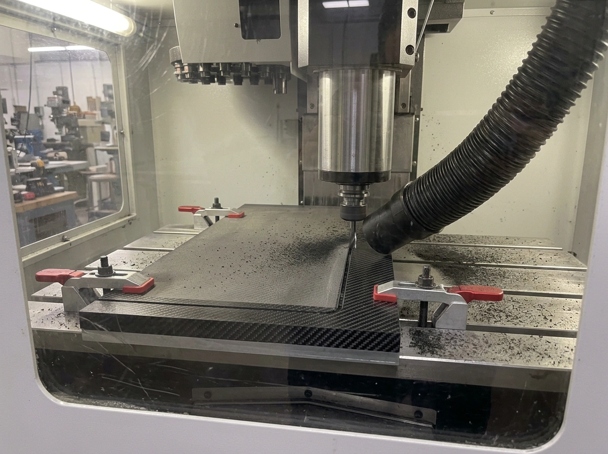
We machine CFRP with tooling and fixturing built for the failure modes the material actually has: diamond-grit or PCD cutters wherever the finished surface matters, with carbide still earning its place on roughing passes; dedicated extraction at the cut; and 5-axis routing where the geometry demands a single-setup pass instead of a re-fixture that invites chipping.
What we handle
- Standard through Ultra-High Modulus and Ultra-High Strength grades, specified the way your drawing names them.
- Milling, drilling, edge trimming, and routing on plate, tube, and contoured laminate stock.
- Dust-controlled shop practice, including extraction at the cut—no CFRP-specific exposure standard exists anywhere, so we run to general respirable-dust thresholds and appropriate PPE rather than claim one that does not exist.
Why composites need a different shop setup
Metals give you chips. Plastics give you stringy swarf. Carbon fiber gives you an abrasive dust cloud that wears tooling in hours, contaminates nearby equipment, and creates a respiratory hazard the moment extraction fails. A shop that quotes CFRP the same way it quotes 6061 aluminum is telling you something about how the job will actually run.
The short version: diamond-grit or PCD tooling wherever the finished surface matters, with carbide still earning its place on roughing passes; dedicated extraction at the cut; a cutting strategy that avoids delamination on the ply closest to tool exit; and fixturing that supports thin laminate sections without crushing them. Nothing exotic — but nothing you can skip either. The rest of this page is the grade list, the property-by-industry map, and the RFQ questions we will ask before quoting.
Why parts end up in carbon fiber in the first place
Six properties come up in every carbon-fiber conversation. Some drive the spec, some drive the quote, and some are just why the part exists at all.
Strength-to-weight
The reason carbon fiber exists on most drawings: comparable load capacity to steel at a fraction of the mass. Aerospace brackets, UAV structures, and racing chassis pay the cost premium because the weight save is the whole point.
Stiffness
Holds its shape under load with very little deflection, which matters on optical mounts, robot links, and instrument housings where a fraction of a millimeter of flex would degrade accuracy.
Thermal stability
Low coefficient of thermal expansion compared to metals — useful when a part has to keep alignment across a wide temperature range instead of drifting with the season or the run.
Corrosion resistance
The fiber itself does not rust or oxidize, and the resin matrix handles most environments short of specific solvents. Galvanic contact with aluminum is the trap — call it out on the drawing so the routing reflects the isolation hardware.
Radiolucency
Transparent to X-rays, which makes CFRP the default for imaging tables, radiology positioning hardware, and certain prosthetic components where the part must not shadow the scan.
Finish and appearance
Twill and plain-weave laminates finish to a recognisable cosmetic surface that a lot of consumer and performance products treat as part of the brand. If the weave pattern is visible on the final part, we plan machining so the cut does not intersect a show face.
Carbon fiber grades and what they are actually used for
Six common grades span the usable range from cost-effective structural parts to specialist aerospace and defense work. Indicative cost column, not a quote — real price depends on lot, cure state, geometry, and finish scope.
| Grade | Characteristic | Typical use | Cost tier |
|---|---|---|---|
| Standard Modulus (SM) | Balanced strength and stiffness, widely available | General aerospace brackets, automotive structural parts, sports equipment | $ |
| Intermediate Modulus (IM) | Higher stiffness without giving up much strength | Performance vehicles, drones, robotics arms and links | $$ |
| High Modulus (HM) | Significantly stiffer, moderate strength | Satellite structures, precision instruments, optical benches | $$$ |
| Ultra-High Modulus (UHM) | Maximum stiffness, lower tensile strength | Vibration-sensitive assemblies, specialist metrology hardware | $$$$ |
| High-Strength (HS) | Very high tensile strength for impact and fatigue loads | Military armor panels, high-end sports equipment | $$$ |
| Ultra-High Strength (UHS) | Peak tensile strength with moderate stiffness | Advanced aerospace structures, defense systems | $$$$ |
Weave, thickness, and what the drawing should name
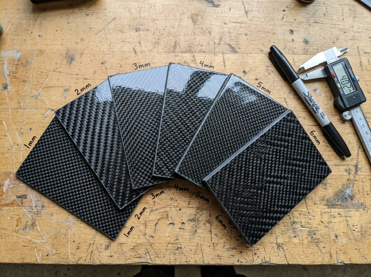
Carbon fiber stock is anisotropic — strength and stiffness run along the fibers, not across them — so weave pattern and fiber direction change how the part behaves under load and at a trimmed edge. Plain weave, 2x2 twill, and unidirectional each take tools and fixturing differently, and the laminate thickness matters as much as the grade. A 1 mm sheet does not finish the same way as a 6 mm block. If the weave is visible on the final part — which is often the case on consumer, automotive, and motorsport work — the routing is planned so the cut does not intersect a show face.
The grade then sets the stiffness-versus-strength tradeoff. Standard Modulus stock covers general structural brackets and sports equipment at the low end of the cost ladder. Intermediate Modulus adds stiffness without giving up much strength, useful on drones and robotics links. High and Ultra-High Modulus grades get stiffer at the cost of tensile strength and go on satellite structures and optical benches. High-Strength and Ultra-High-Strength grades point the other way — peak strength for impact and fatigue loads on defense and advanced aerospace parts.
A useful RFQ names the laminate spec, the fiber direction if it matters, and whether the part has a resin-rich cosmetic surface or a trimmed functional edge. Add any galvanic isolation requirements if the part contacts aluminum. Those lines turn a generic "carbon fiber part" into a quote we can route against real tooling, extraction, and first-article strategy — instead of a line-item guess that gets revised the moment the first setup runs.
Why carbide dies on carbon fiber, and what actually replaces it
Carbon fiber does not cut metals wear tooling—it abrades it. That single difference decides the tool material, and it is worth understanding rather than taking on faith.
Abrasion is the only active wear mechanism when a tool cuts fibre-reinforced plastic: the flank polishes rather than cratering, and average roughness rises roughly linearly with cutting length—the tool is consumed on a schedule, not by sudden failure. That happens because the reinforcement fibre is harder than the hard phase in the carbide itself, so wear proceeds by microcutting. The practical mitigation is to run a carbide grain size larger than the reinforcement, and it is also why HSS and conventional twist-drill geometries are effectively obsolete on CFRP—short tool life and a tendency to delaminate the material on exit have practically eliminated them from this work.
| Tool material | Where it belongs on CFRP | Why |
|---|---|---|
| HSS | Effectively obsolete | Short tool life and a tendency to delaminate the material on exit |
| Cemented carbide | Roughing — best cost/benefit despite higher wear | Wears smoothly on the right grade rather than catastrophically; flank wear rises slowly at moderate cutting speed, then much faster past it |
| Ceramics / SIALON | Not recommended | Feed force shows a marked rate of increase across cutting length |
| Diamond coating (CVD/DLC) on carbide | Finishing, trimming, drilling | Hardness in excess of 8,000 HV, from the sp³ structure, qualifies it for GFRP and CFRP |
| PCD | Finishing — the only material suitable for finish turning | Feed force stays almost constant across cutting length, the same order as steel; trade-off is micro-chipping from intrinsic brittleness |
Turning trials across carbide, ceramics, SIALON, CBN and PCD on carbon/glass-fibre stock found that only diamond tools are suitable for finish turning, while cemented carbide remains the best cost/benefit choice for rough turning despite its higher wear rate—which is why we route roughing and finishing to different tool materials rather than run one grade through the whole job.
Delamination: peel-up, push-out, and what actually prevents it
Delamination is the defect that gets a part rejected, and it has two distinct mechanisms that call for different fixes—not one generic "go slower."
Peel-up happens at hole entry, where tool geometry lifts the top plies. Push-out happens at exit, and it is the more common failure: the thrust force needed to cause delamination collapses as the uncut depth of material below the drill point shrinks toward the last ply, which is exactly why exit damage concentrates there rather than mid-laminate. Counterintuitively, controlled drilling trials found that drill geometry dominates delamination risk far more than cutting speed does—geometry and feed were statistically significant for maximum thrust force, cutting speed was not. Geometry beats parameters, which is why our process controls target the drill and the backing, not just the feeds and speeds.
| What you see | Where | What changes it |
|---|---|---|
| Peel-up delamination | Hole entrance | More negative tool geometry; reduce feed per revolution |
| Push-out delamination | Hole exit | Back support—wood, aluminum, or plastic; reduce feed on the exit ply; double-point-angle drill |
| Uncut fibres / spalling at the edge | Trimmed edge | Sharper, more positive tool geometry; reduce feed per revolution |
| Melted or smeared resin | Any cut | Reduce cutting speed—the tool is generating more heat than the resin can absorb |
| Internal delamination, no visible surface defect | Mid-laminate | Change drill geometry—chip imprisonment from the wrong flute form is a geometry problem, not a feeds-and-speeds one |
On thin laminates—2.5 mm and under are especially vulnerable—the outside plies are always backed externally, and feed is reduced specifically on the exit layer rather than held constant through the stack: a practical split runs roughly three times slower on the last ply than the first. Standard twist-drill geometry (118° point, 30° helix) is not the composite answer; a point angle in the 130–140° range with helix above 24° both reduces delamination risk and minimises surface roughness. Where the design allows it, trimming with compression (opposed-helix) router geometry directs cutting forces inward and gives quality edges on both faces at once, which removes the peel-up/push-out choice entirely for that operation.
What tolerance is realistic on a laminate—and why it is not the metal number
"What tolerance can you hold on carbon fiber?" is really three questions: what does the general tolerance standard actually control, why does a laminate diverge from a metal cut in the same class, and what has to go on the drawing before either answer means anything.
ISO 2768-1—the standard behind the general tolerance table on our CNC machining page—states plainly that it applies to parts produced by metal removal or formed from sheet metal, with a note that its classes may be suitable for materials other than metal. That is the honest, standards-grounded way to say the general tolerance class on a composite drawing is an assumption carried over from metal, not a laminate-specific figure. The same standard is explicit that exceeding a general tolerance does not automatically make a part rejectable if function is not impaired—which is exactly why the features that carry function on a laminate need their own individual tolerances rather than a blanket class.
The divergence is measurable. On a hole drilled through a titanium/CFRP stack with the same tool, published aerospace acceptance criteria run about twice as coarse on the composite side as on the metal side of the same hole—and measured results follow the same pattern:
| Measurement | Titanium phase | CFRP phase |
|---|---|---|
| Aerospace acceptance criterion (Ra) | ≤1.6 µm | ≤3.2 µm |
| Measured Ra, drill A | 0.511–1.073 µm | 2.016–5.100 µm |
| Measured Ra, drill B | 0.373–1.301 µm | 1.146–4.919 µm |
The mechanism is fibre pull-out: at the instant of chip separation the brittle fibre fractures cleanly while the softer resin continues to deform, leaving micro-cavities that a metal cut does not produce. On the same part machined with the same tool, one published study measured the deepest surface valleys on the composite side at nearly four times the depth of the metal side—that is the pull-out craters, not measurement noise.
There is also a direction-dependent thermal-expansion problem that a metal drawing never has to solve. Carbon fibre itself has a coefficient of thermal expansion close to zero along its axis—occasionally slightly negative—while the resin around it expands closer to the rate of aluminum or faster. A laminate does not have a coefficient of thermal expansion; it has one that depends on direction and lay-up:
| Material | Coefficient of linear thermal expansion |
|---|---|
| Carbon fibre, axial | Near zero, occasionally slightly negative |
| Steel | 11 ppm/°C |
| Aluminium | 22 ppm/°C |
| Epoxy resin (glass-reinforced) | 36 ppm/°C |
| Epoxy resin (unfilled) | 54 ppm/°C |
Moisture adds a second variable a metal drawing does not carry: composite dimensional change is a function of both temperature and moisture condition, and moisture diffuses through a laminate many orders of magnitude slower than heat does—so a part measured immediately after machining and the same part measured after conditioning can disagree for reasons that have nothing to do with the machining itself. The tolerance conversation on a laminate therefore needs three things on the drawing that a metal drawing does not: the general tolerance class, with an acknowledgement that it was written for metal; the measurement temperature; and the moisture condition the part will be measured in. Without those three, a tight tolerance on a composite drawing is not a requirement anyone can actually verify. See plastic machining for the same thermal-expansion argument applied to unreinforced engineering plastics.
Fibre orientation: same tool, same part, four different surfaces
The page already says CFRP is anisotropic. What that means in practice is that identical tooling can leave a noticeably different edge depending purely on which way the fibres run relative to the cut.
0°
Well-aligned fibres are not cut cross-sectionally at all. Roughness stays low and is essentially insensitive to depth of cut—the best case, and where a show face or critical edge exists, we orient the routing to it.
45°
The chip forms by shearing at the fibre/matrix interface with consecutive fibre breakage. Roughness roughly doubles versus 0° at every depth of cut, driven by elastic return of fibres compressed under the tool tip.
90°
The tool presses the laminate until a crack appears along the fibre/matrix interface, propagating obliquely below the surface—subsurface damage, not just a rougher finish.
135°
Fibres are inclined against the cutting direction, generating thrust from the downsloping pressure on the tool. That thrust deflects the tool and reduces depth of cut—this orientation costs tolerance, not just finish.
Roughness peaks specifically at 45° and 225° to the cutting direction, and in trimmed stacks the 90° and 135° orientations show markedly poorer surface quality and more subsurface fibre/matrix damage than 0° and 45°. None of that is a defect in the part—it is physics that a fixed feed and speed cannot fully compensate for, which is why the routing plan, not just the cutting parameters, changes around the edge of a real part.
Where CFRP parts actually end up
Every industry that puts carbon fiber on a drawing does it for a slightly different reason. The list below is the pattern we see on RFQs; yours will match one of them or sit between two.
Aerospace & UAV
Structural panels, ribs, and drone chassis where removing a kilogram reduces fuel burn or payload cost directly. Usually Standard or Intermediate Modulus grades on production parts, High Modulus on spaceflight work.
Automotive & motorsport
Racing chassis components, EV battery housings, aerodynamic bodywork. Cosmetic weave visibility is often part of the brief as much as the mechanical load rating—see automotive machining for the broader program context.
Medical & imaging
Radiolucent tables, positioning jigs, prosthetic sockets, and some orthopaedic brackets. Biocompatibility and the radiolucency requirement drive the grade choice more than cost—see medical machining.
Sports & recreation
Bike frames, racket frames, hockey stick shafts, high-end protective gear. Usually a blend of SM and HS grades to hit a specific stiffness-plus-impact profile for the sport.
Marine
Hardware and structural components for yachts, racing sailboats, and instrumentation housings where a stainless equivalent would corrode. Galvanic isolation on fastener interfaces goes on the drawing, not the quote—see metal machining for the stainless and aluminum side of a mixed-material assembly.
Consumer electronics
Premium laptop and phone chassis, camera gimbals, and drone arms where the weight-and-feel signal is as important to the buyer as the mechanical spec.
Machined from laminate, or moulded to net shape?
The upstream decision most RFQs skip: whether a part should be machined from cured stock at all, or moulded closer to final shape first.
Composites are usually moulded, but achieving close fits and tolerances, or reaching true near-net shape, still requires some machining—and because of their non-homogeneity, composites pose real problems that metal-machining data cannot answer. Machining a cured laminate also cuts fibres, which weakens the local structure and creates stress concentrations; a poor cut edge becomes an in-service crack initiator rather than a cosmetic issue, which is exactly why cut quality and edge planning matter as much on a structural CFRP part as the dimension itself.
Moulding is not a free path around tolerance, though—it has its own, wider bands. Normal thickness variation runs from about ±0.13 mm on matched-die processes up to ±0.51 mm on hand lay-up, and a published class table for reinforced-plastic parts puts even the "fine" class at roughly ±0.5 mm for a 100–200 mm dimension—which sits at ISO 2768 class c, not the tighter classes a metal part might carry. That is the honest starting point for a moulded composite, and it is why features that need to hold function on either a moulded or a machined laminate get individually toleranced rather than left to a general class.
The producibility literature makes the opposite point just as plainly: acquiring a part in final net shape reduces machining and fabrication time and cost, but that does not mean net-shape moulding is automatically cheaper—a design guidance handbook puts it directly: do not necessarily assume the near-net-shape process is the most economical; always compare the cost of both methods before deciding. Mechanical joints stay common for exactly that reason—drilling remains the most-used technique for composite assembly despite laser and waterjet alternatives being available—so the real question on a new part is not "moulded or machined" in the abstract, but which one gets your specific geometry and tolerance to the drawing for less. Send both the geometry and the volume (see rapid prototyping for early-stage builds) and we will tell you which side of that line your part sits on.
Dust, extraction, and why the cut usually runs dry
Carbon fiber dust is not just a housekeeping problem. It is electrically conductive, which makes it a machine-protection issue as much as an operator-safety one—and there is no single published exposure standard written for it.
Dust extraction is required for both reasons at once: carbon dust is electrically conductive, so beyond the respiratory hazard it can affect electrical components and increase spindle wear if it is allowed to migrate through the machine. That conductivity is a real physical property, not a marketing point—graphite and graphite-containing composites are treated as a metal for the purposes of dissimilar-metal contact, which is also the source of the galvanic warnings elsewhere on this page.
The particles themselves are fine enough to matter: individual carbon fibres run roughly 5–10 µm in diameter, and composite machining generates predominantly sub-10 µm dust, with some fragments as small as 0.05–0.1 µm—fine enough to penetrate deep into the lungs. No CFRP- or GFRP-specific occupational exposure limit exists anywhere in the world—general dust thresholds are applied instead, and a stricter airborne-fibre limit has been proposed but is not yet universal. Controls run to that general standard: HEPA filtration, local exhaust ventilation, fine-particle-capture vacuums, and encapsulation of the machining zone, with PPE appropriate to composite dust rather than to a standard that does not exist.
Because composites cut by brittle fracture rather than shear, coolant is often unnecessary—abrasive wear from the fibres is the dominant tool-life mechanism, and cutting fluid has limited effect on either tool life or achievable finish, though it can help with swarf disposal. That is why CFRP work typically runs dry. The honest exception is stacked work: on CFRP/metal stacks, cutting fluid helps prevent chip clogging in the flutes and can improve surface quality on the composite side, and heat generation on some cuts is damaging enough that cooling is genuinely required. Which regime applies is a routing decision made per part, not a blanket rule—and it is never made on the theory that CFRP avoids coolant because the laminate absorbs water; that is not the reason, and we do not claim it.
Carbon fiber machining FAQs
Carbon fiber RFQ
Scope a composite part with the right shop
A carbon fiber quote that doesn't mention tooling, extraction, or ply orientation is missing something. Send the 3D, the 2D drawing, and the grade — we come back with a routing plan that respects what CFRP actually needs.