
CNC Milling Services in China
Precision milled metal and plastic parts for OEM programs: 3-axis through 5-axis when your geometry demands fewer setups and better feature relationships. Quotes tie to your 2D drawing and CAD—datums, tolerances, and finishes stated before programming and cutting.
At a glance
- Prismatic parts: pockets, bosses, holes, profiles, and contoured surfaces per your release.
- Tolerances, threads, and inspection intent taken from the drawing—not generic defaults.
- Prototype through production volumes; lead times and finishes quoted per scope.
CNC milling for OEM prismatic parts
CNC milling is how most brackets, housings, plates, and structural components get made: rotary cutters remove material under program control while the workpiece stays fixtured on a milling center. For teams sourcing precision CNC milling in China, the win is not a slogan—it is clear scope, stable drawing interpretation, and inspection that matches what you released.
China Precision CNC plans milling around access, datum scheme, and tolerance stack-up on your PDF. When complexity or tight feature-to-feature relationships justify it, 4- and 5-axis paths can reduce repositioning and protect relationships that matter to assembly.
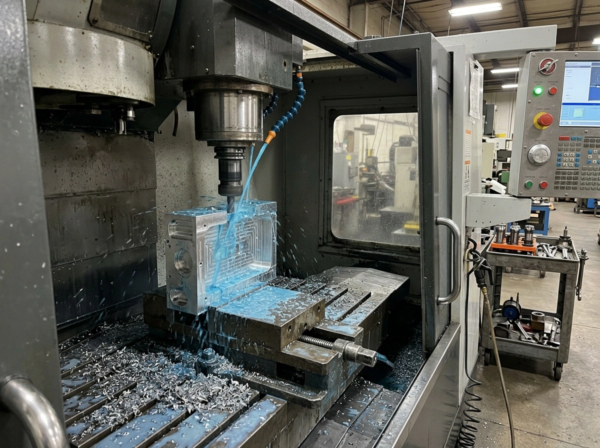
What CNC milling covers
Milling removes material with rotating tools to create flats, pockets, slots, holes, threads, and contoured surfaces. The six operation types on the right—face, end, slot, profile, thread, and angular milling—cover the vocabulary.
The question that actually decides your quote is not which operation type applies. It is how many axes the job needs and why. Axis count is not a complexity score—it is set by which faces your features sit on and whether they have to stay related to each other once the part comes off the fixture. The next section works through that decision properly, because "we run 3, 4, and 5-axis" tells you nothing about which one your part needs.
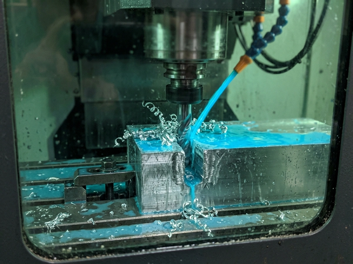
Milling operations we support
Descriptions below are educational; exact tooling paths, feeds, and inspection are locked to your quote and drawing revision.
Face milling
Large-area facing for seal lands, mounting faces, and parallelism-driven surfaces—often early in the operation sequence.
End milling
Pockets, steps, and internal vertical walls; workhorse approach for most prismatic geometry.
Slot milling
Linear slots and narrow reliefs where width and position drive function or assembly.
Profile milling
Outside contours and blended shapes where the silhouette defines fit or airflow.
Thread milling
Thread forms produced with thread mills where the plan and drawing specify that approach.
Angular features
Chamfers, angled faces, and dovetail-style work per callout—often combined with secondary fixturing or multi-axis positioning.
Axes, and what each one can actually reach
3-axis, 4-axis, and 5-axis are not a ladder of quality—they are different answers to where your features sit and whether they have to stay related to each other after the part comes off the fixture.
3-axis
A vertical spindle with three linear axes (X, Y, Z)—the workpiece is addressed from one direction per setup. Features reachable from one or two faces cost least here, and most prismatic parts should start on 3-axis before anything else is considered.
4-axis
A horizontal spindle with rotary table motion around a fourth axis, addressing a pattern of features around a cylindrical face without refixturing each one. A good compromise between flexibility and cost, and the natural fit for multi-side production on a tombstone fixture.
5-axis
Two rotary axes added to the three linear ones, letting the tool reach compound angles and deep pockets in one clamping. On larger parts the rotary motion is more often built into the spindle head instead of the table, because precisely rotating a large workpiece is often impractical.
What decides the configuration is not how complex the part looks. It is the workpiece dimensions and orientation, the axis motions the features actually require, and the fixturing those motions leave room for—which is the honest version of "5-axis when the geometry demands it." If a part turns out to be rotational rather than prismatic, or needs EDM or grinding instead, the hub's guide to choosing between routings covers that call.
3+2 positional vs. simultaneous 5-axis
This is the distinction buyers most often get wrong, and it is worth five minutes before the RFQ goes out—one of these buys you a shorter tool and nothing else, and the other buys continuous contouring at a real premium in programming.
3+2 (positional)
The two rotary axes orient the part, then lock. The cut itself is a three-axis cut taken from a tilted approach. What that buys you: access to a compound-angle face without a new fixture, and—because the tool can be brought closer to perpendicular to the surface—a shorter tool. What it does not buy you: continuous contouring of a curved surface.
Simultaneous (continuous) 5-axis
All five axes move during the cut, so the tool axis changes continuously relative to the surface. Required for true sculptured surfaces—impellers, blends, compound-curvature cavities. It costs more in programming and verification than it does in machine time.
Why the shorter tool matters
Tool overhang reduces rigidity as the cube of its length, while tool diameter increases rigidity as the fourth power of diameter. That relationship—not the axis count—is the actual mechanism behind "5-axis gives a better finish." A useful working rule: keep tool and holder deflection under 0.025 mm.
Most parts that "need 5-axis" need 3+2. Specifying simultaneous 5-axis on a part that is a set of flats at compound angles buys programming time and nothing else—tell us which one your drawing actually requires, or send the feature list and we will tell you.
Materials & finishes
We mill common aluminum and steel alloys, stainless, titanium, brass and copper alloys, and engineering plastics—grade and lot requirements are confirmed at quote. Machinability, stress, and thermal behavior drive tool strategy; your drawing notes and material callouts stay in scope.
Surface finishing after milling—anodize, plate, blast, coat, and more—is quoted and scheduled with the milled part in mind. See surface finishing, and for grade-level detail see metal machining and plastic machining.
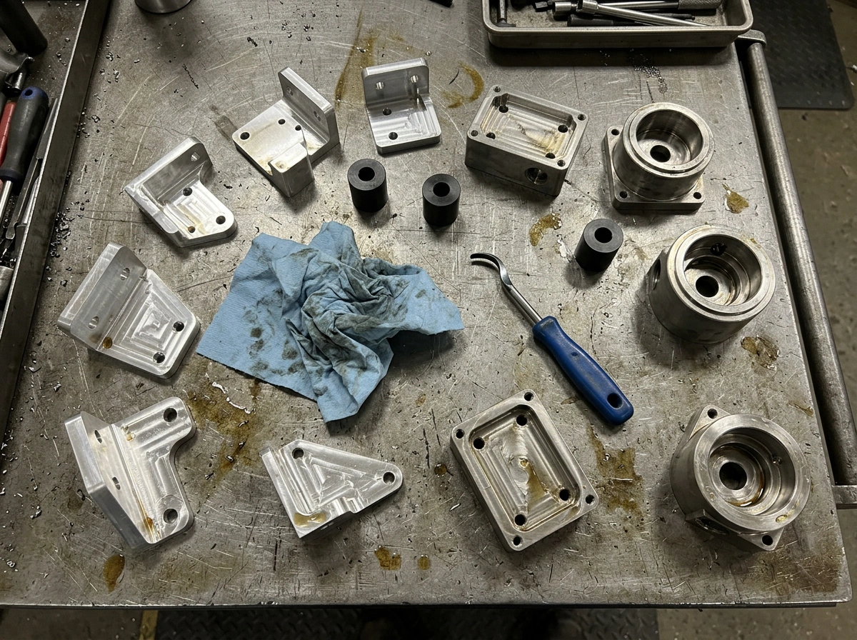
Setups: the number that moves your quote most
Every setup is a re-fixturing, a new datum reference, and a stack-up risk. The mechanics behind that are worth knowing before the design locks, because most of the cost is decided in CAD, not on the machine.
Workholding follows the 3-2-1 locating principle: the primary plane carries three support points and restricts five possible movements; a second plane carries two points and restricts three more; a third plane carries one point and restricts the last. Six locators between them constrain nine of the twelve motions a rigid body has, and clamps restrain the remaining three. Locators are placed as far apart as possible for stability—and those same locators establish the measurement datums that critical features get toleranced against. That is why the datum scheme on the drawing and the fixture plan are the same conversation, and why a drawing whose datums cannot be located cleanly is a quoting problem before it is a shop problem.
Re-fixturing costs accuracy, not just time. The long-standing shop rule is to do all machining feasible at one setting rather than machine one end and reverse the work, because any error introduced at either end is doubled when the work is reversed. Clamping is a variable too, not a constant: force has to stay below the level at which part deformation becomes significant against the part's tolerance, so finishing operations run on much lower clamping force than roughing.
Locate from holes or edges—never both
Locator positions on the fixture are fixed, while hole positions vary within tolerance. Mixing the two locating schemes on one part fights the fixture against the drawing.
Clamp position restricts the cut
The closer a clamp sits to a machined feature, the more it restricts the operation. Clamp height and position affect the achievable tool diameter, cycle time, finish, and accuracy on everything near them.
One feature, one datum, every time
A feature machined from the same setup as its reference datum holds tolerance more predictably than the same feature toleranced across a re-fixture—independent of how tight the number is.
Toolpath strategy, and why it shows up on your part
"We program it" hides a set of choices that change heat, wear, and finish on the part you get back. None of it needs to be on your drawing, but a feature that behaves oddly usually traces back to one of these.
Climb vs. conventional
In climb (down) milling the cutter rotates with the feed and chip thickness is maximum at entry, near zero at exit—most of the heat leaves in the chip and work-hardening is largely prevented. In conventional (up) milling the tool rubs at the start of the cut, more heat diffuses into the part, and chips fall in front of the cutter and get re-cut. Climb is the default; conventional is still the right call where backlash is present, or on a part with large height variation or a hardened outer skin from casting or flame cutting.
Adaptive roughing and chip thinning
High-efficiency roughing uses the entire flute length by inverting the traditional recipe—light radial depth, heavy axial depth, higher feed—spreading wear evenly along the edge instead of concentrating it. Feed per tooth only equals chip thickness at 50% radial engagement; below that a chip-thinning adjustment applies, with a floor around 0.07 mm average chip thickness—thinner than that, the edge starts rubbing instead of cutting, which produces more heat and faster flank wear.
Corner engagement and entry
An inside radius that exactly matches the tool radius at a 90° direction change is the least desirable condition on a toolpath—engagement angle spikes, and chatter, deflection, and poor corner finish follow. Ramping or arcing into a cut instead of plunging avoids shock loading and produces smaller chips than a straight plunge.
Surface finish: what a milled face can hold, and what it costs
Finish and tolerance are the same conversation, not two separate line items—and the cheapest print is the one that specifies finish by what the surface does, not by habit.
Ra of 1.6 µm (63 µin) or coarser comes out of general roughing and semi-finishing at reasonable cost. Below that, every step down is buying an extra operation. Total profile height runs roughly four times the measured Ra, so as a rule of thumb the roughness on a toleranced diameter should not exceed about one-eighth of the dimensional tolerance on that diameter if the two are going to agree with each other. Over-specifying is common and expensive: a 0.3–0.4 µm finish on a surface that exists only to locate the part for a later operation cannot be justified when a 1.0–1.5 µm finish does the same job for at least 50–60% less.
| What the surface does | Max Ra (µm) | Max Ra (µin) |
|---|---|---|
| Clearance surfaces (machined) | 6.3 | 250 |
| Mating surfaces — brackets, pads, faces, bases | 3.2 | 125 |
| Housing fits, no gasket or seal | 3.2 | 125 |
| Datum surfaces, tolerance over 0.025 mm | 3.2 | 125 |
| Datum surfaces, tolerance under 0.025 mm | 1.6 | 63 |
| Milled threads; press fits, keys and keyways | 1.6 | 63 |
| Sliding surfaces of mating parts, general | 0.80 | 32 |
| Cylinder bores for O-rings | 0.40 | 16 |
What actually drives achievable Ra on a milled face: material and hardness, tool projection and deflection, speeds and feeds, tool-to-workpiece orientation, toolholder runout, workholding rigidity, and coolant. The practical levers are climb milling over conventional, a higher helix angle, more flutes on harder materials, a finishing radial depth of cut around 2–5% of tool diameter, and keeping runout at 0.0003 in or less. One honest limit worth stating plainly: end milling cannot match boring or reaming for finish, and milled finish marks run around the perimeter of a feature rather than along it—if the drawing wants a bore finish, the routing needs a bore, not a smaller stepover.
Design rules that decide the price of a milled part
Material is removed by a round tool spinning at speed, so an interior vertical wall is always machined with a radius—whether or not the drawing specifies one. The size of that radius is one of the most durable levers on a milled part's cost.
| Feature | What governs it | What to put on the drawing |
|---|---|---|
| Internal corner radius | A rotating tool cannot cut a sharp internal vertical corner—the radius exists whether you specify it or not | Specify it, and make it generous. Roughing prefers a programmed radius near 50% of cutter diameter; finishing wants a cutter no larger than 1.5× the component radius (a 10 mm corner radius takes a 15 mm cutter at most) |
| Opening that radius up | A larger radius allows a larger roughing cutter and a higher removal rate | Widening one pocket's corner radius from 9.5 mm to 25.4 mm can eliminate a tool change entirely on that feature—small changes here compound across a production run |
| A radius matching the finishing tool exactly | Engagement angle spikes at a 90° direction change | Avoid matching the tool radius precisely; expect chatter, wall taper, and poor corner finish if you do |
| Internal corners normal to the base | Tool access from a single setup | Sharp internal corners parallel to the base machine readily; normal to the base, avoid them where function allows |
| Pocket depth vs. tool diameter | Rigidity falls as the cube of tool overhang and rises as the fourth power of tool diameter | State pocket depth and the smallest required corner radius together—together they fix the tool, and the tool fixes the feed |
| Thin walls | Cutting pressure against an unsupported wall | Machined with a progressive radial depth of cut, alternating sides, climb milling; wax or thermoplastic stabilisation where fixturing cannot reach |
| Holes by depth | Length-to-diameter ratio decides the method | Reaming works at any L/D; boring below L/D 10; circular interpolation below L/D 4. Boring and reaming hold tighter tolerances than interpolation |
| Repeated radii across one part | Every distinct radius is a tool change | Standardise radii across the part where function allows—one tool then serves several features |
The pattern behind all of it: the largest single change most drawings can make is opening internal radii wherever function allows. It is usually the cheapest edit available, and it costs nothing but weight and volume—the trade-off worth running before the design locks rather than after the first quote comes back higher than expected.
From RFQ to delivery
A typical milling program flows through review, setup, cutting, and receipt—exact milestones match your PO and drawing revision.
Design review
We review CAD and PDF for manufacturability, datum alignment, and tolerance risk before locking the process plan.
Material
Grade and stock form are aligned to your specification and the quote; changes flow through revision control.
Programming & setup
Toolpaths, workholding, and first-article intent are defined for the agreed scope and machine class.
Milling
Production follows the released process; in-process checks align to critical features on your drawing.
Inspection
Dimensional and thread verification planned around fit, function, and safety—not generic full layouts unless required.
Finishing & delivery
Approved finishes applied per PO; packing and documentation match your receiving workflow.
Typical milling capability snapshot
Limits depend on material, size, and inspection—always confirmed in your quote. Use this table as a planning guide.
| Feature | Typical notes (CNC milling) |
|---|---|
| Axes | 3-axis, 4-axis with a rotary, and 5-axis in both 3+2 positional and simultaneous modes—chosen from what your drawing's features need to reach, not from part size. See axes and what each one reaches |
| Work envelope | Discussed per job—part size and fixturing drive machine selection |
| Setups | Driven by how many faces carry features and which feature relationships must hold—the largest single lever on a milled part's price. See setups |
| Tolerances | Quoted against the general tolerance class marked on your drawing—see ISO 2768 tolerance classes—with tighter individually toleranced features called out separately |
| Surface finish | Specify Ra per surface, by function. 1.6 µm and coarser is routine from milling; tighter bands add operations. See achievable finish |
| Lead time | Quoted per BOM, complexity, and queue—prototype vs production schedules differ |
| Materials | Metal machining and plastic machining for grade-level detail |
| Related | Broader machining scope: CNC machining; rotational work: CNC turning |
Why choose China Precision CNC for CNC milling?
After your geometry and drawing are in hand, sourcing comes down to clear scope, realistic schedules, and inspection that matches what you released—not generic defaults.
Quote-aligned scope
Structured RFQs with assumptions spelled out—material, tolerances, threads, and finishes tied to your PDF revision so both sides agree before programming and cutting.
Scalable volumes
First articles through recurring production: routing, fixturing, and documentation scale with your program instead of forcing a one-size process on every job.
Schedules you can plan against
Lead times and milestones are quoted per scope—complexity, inspection load, and queue position drive dates, not blanket promises.
Drawing-first precision
Datums, tolerance stack-up, and critical features come from your drawing; inspection targets the features that matter for fit and function.
Materials & finishing paths
Common metals and engineering plastics; post-milling finishes coordinated with geometry and your PO. Finishing overview: surface finishing.
CNC milling FAQs
Start your RFQ
Request a CNC milling quote
Send your CAD and 2D drawing. We will respond with a structured quote and explicit assumptions for your milled parts.