
New Energy CNC Machining in China
Battery, fuel cell, electrolyzer and power electronics hardware is a sealing and flatness problem before it is a machining problem. The part has to close a joint, carry a coolant or a current, and stay flat after it leaves the fixture. The dimension that looks tightest on the drawing is rarely the one that decides whether the stack seals.
We machine this hardware for prototype, validation and bridge production runs. The quote tells you how we plan the fixturing, the deburring and the inspection for each line, so the cost reflects the real work and not a worst-case guess.
What we handle
- Battery enclosures and trays, cold plates, fuel cell end plates and bipolar plates, electrolyzer components, inverter and converter housings, busbars and EV charging hardware.
- Aluminum 6061 and 6063, C110 ETP copper, stainless steel and engineering plastics, sourced against the grade and condition on your drawing.
- Anodize, chemical conversion coating and plating, planned into the machined dimension before the first part runs.
Why does new energy hardware start with sealing and flatness?
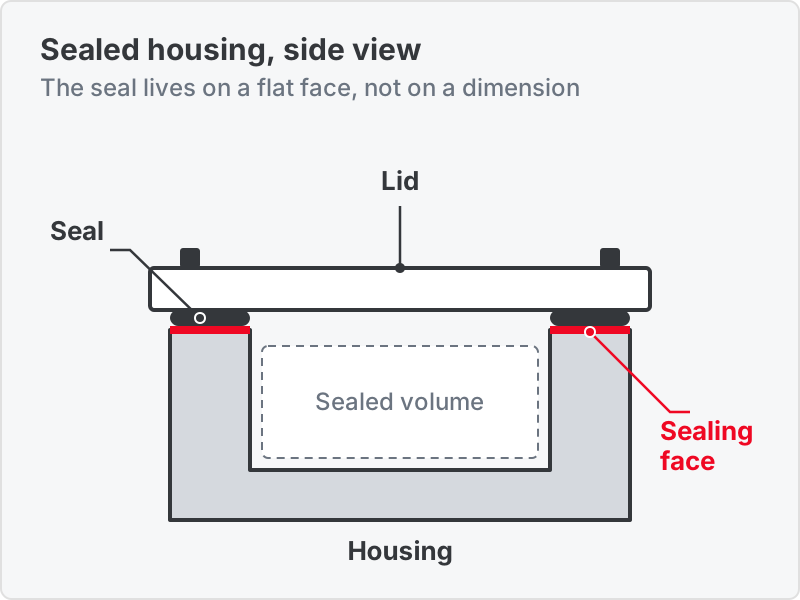
Most new energy parts do one of three jobs. They hold a pressurized or sealed volume, they move heat out through an internal passage, or they carry current through a contact face. Each job lives on a surface, not on a single tight dimension. A cold plate that is dimensionally perfect still leaks if the sealing face is out of flat. A busbar that is on size still runs hot if the contact face is smeared or burred.
That changes what a good RFQ looks like. The drawing has to say which faces seal, which faces conduct, and which faces only locate. Parts that are large, thin and flat also move when they are unclamped, so flatness has to be agreed as free-state or constrained before the first part is cut. The sections below show how we plan each part family and what we need on the drawing to quote it.
Which new energy parts can be CNC machined?
Seven part families cover most of the new energy work that lands here. Yours probably matches one of them or sits between two. Describe the function of the part and we can usually name the right machining pattern from a one-paragraph brief.
Battery enclosures and trays
Pack enclosures, trays, cell holders and module housings. Aluminum 6061 and 6063 cover most enclosure and thermal-path parts, and cell holders often run in machined plastic. Sealing-face flatness and the lid or cover interface drive the plan more than the outside profile.
Cold plates and cooling plates
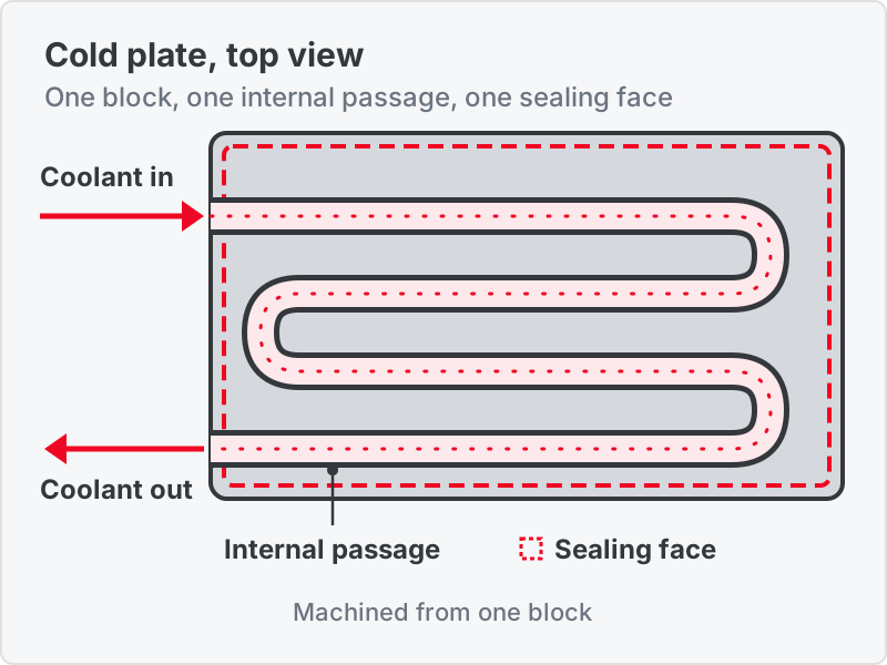
Passage geometry is a manufacturability decision made in CAD. A serpentine channel a cutter can reach is one part. A passage that forces a split plate and a joining operation is a different part with a different cost and a leak path. Ask the question before the design locks.
Fuel cell end plates and bipolar plates
End plates, manifolds, port plates and metallic bipolar plates in aluminum and stainless steel. These are large, thin, flat parts. Distortion, fixturing and flatness verification are the whole conversation, and material is a corrosion decision before it is a machining one.
Electrolyzer components
Plates, frames and manifold parts for electrolyzer stacks share the same sealing-face and flatness problems as fuel cell hardware. Send the material specification and the sealing scheme with the RFQ, and we confirm the machining route before we quote.
Inverter and converter housings
Aluminum housings that have to seal, conduct heat out and locate a PCB stack. Sealing-surface flatness, bore position and thread condition are the features that matter. The outside profile usually is not, so say which is which on the drawing.
Busbars and current-carrying parts
C110 ETP copper is soft and smears, so burr control and edge condition drive the tooling choice rather than cycle time. Contact faces need a flatness and finish callout. If plating follows machining, the plating takes dimensional budget that has to be planned in.
EV charging hardware
Charging port components, connector bodies and contact hardware. These are small, conductive and sealed parts, so the contact surface, the seal groove and the plating allowance are the features to call out.
Mixed-material assemblies and wider BOM scope route through our CNC machining service. For the underlying processes see CNC milling and CNC turning, and for enclosure and bracket work in sheet see sheet metal fabrication. Vehicle structure, powertrain and chassis parts sit on the automotive CNC machining page.
How are fuel cell and electrolyzer stack plates machined?
Flatness over a large thin area, controlled by fixturing and by what happens after unclamping. Stack hardware is end plates, manifolds, port plates, cooling plates, sealing grooves and bipolar plates. Each has a different thing that drives the plan and a different thing that must be on the drawing.
| Component | What drives the machining plan | What has to be on the drawing |
|---|---|---|
| Bipolar plates (metallic) | Thin section over a large area, so clamping and cutting forces both distort the part. Flow-channel depth consistency matters more than any single dimension, and the plate has to stay flat after it comes off the fixture | Flatness over the sealed area with its datum scheme, channel depth tolerance, surface condition in the contact region, and whether flatness is checked free-state or constrained. We machine these in stainless and aluminum. Send the material specification if your design calls for graphite or a coated substrate, so we confirm the route before quoting |
| End plates and compression hardware | Stiffness is the point, because these carry the stack compression load. Bolt-pattern position and parallelism between the two loaded faces decide whether the stack seals evenly | Parallelism between loaded faces, positional tolerance on the bolt pattern, and the assembly torque the design assumes |
| Manifolds and port plates | Cross-drilled intersections, internal burrs that no inspection sees, and a sealing face around every port. Deburring internal intersections is real, quotable work | Internal cleanliness and deburr requirement, port sealing-face finish, and whether pressure or leak testing is in scope and to what standard |
| Coolant channels and cooling plates | Passage geometry against machinability: features a cutter can reach, or a plate machined in two halves and joined. That decision belongs in design, not in quoting | Passage cross-section and minimum internal radii, joint method if the plate is split, and the leak-test pressure and acceptance criterion |
| Sealing surfaces and gasket grooves | Groove width, depth and corner radius against the gasket the design assumes. Surface finish in the groove is a sealing requirement, not a cosmetic one | Gasket part number or cross-section, groove tolerances, and the surface finish callout with its measurement direction |
| Material and corrosion | The stack environment is humid and acidic, so the material and any coating are corrosion decisions. Stainless grades and coated substrates behave very differently under the cutter and in service | Grade and condition, any coating specification, and the contact-resistance or conductivity requirement if the part carries current |
Almost none of these parts are defined by one tight dimension. They are defined by form across a large surface, by what happens after the part is unclamped and by what the sealing face has to do. An RFQ that sends the model and the flatness scheme together gets a useful quote. One that sends the model alone gets questions.
We verify flatness and parallelism on our own coordinate measuring machines, and we agree free-state or constrained measurement with you before the first plate runs. If the program needs prototype plates before the design locks, see rapid prototyping.
How do cold plates, trays and housings go from prototype to production?
Start with the question that decides the part: can a cutter reach every passage and every sealing face? If yes, the part machines from one block and the leak path is only the seal. If no, the part is split and joined, and the joint becomes a leak path with its own inspection. Settle this at the prototype stage, while the design can still change.
Three habits carry the part from prototype to production. First, fix the sealing-face flatness requirement and how it is measured at the first prototype, so every later lot is judged the same way. Second, specify internal deburring for galleries and cross-drilled intersections. Drilled intersections leave burrs where nothing can see them and everything can feel them, and "deburred" means something different to every shop. Third, state the leak-test requirement on the drawing, with pressure and acceptance criterion, so the routing and the inspection plan are built for it from the start.
Large aluminum parts with thin webs also carry residual stress from the stock. A part can measure flat on the machine and be out of flat by the time it reaches inspection. Stress relief between roughing and finishing is the usual fix, and it belongs in the routing.
Which materials suit new energy parts?
Aluminum for housings and plates, copper for current, stainless for corrosive environments, and plastics for insulation. Call out the grade and condition on your drawing and we work to it.
Aluminum 6061-T6 and 6063-T5
The default for battery enclosures, inverter housings, cold plates and end plates. 6063 is the extruded-friendly grade for cooling hardware. 6061 is the all-rounder for milled enclosures and plates.
Copper alloys (C110 ETP)
For busbars and current-carrying parts where electrical conductivity matters. Soft and prone to smearing, so burr and edge control set the tooling plan.
Stainless steel
For stack plates and fluid-contact parts in humid or acidic environments. Grade selection is a corrosion decision first. See the stainless steel machining guide.
Engineering plastics
Cell holders, insulation parts and spacers where a polymer is preferred to metal for insulation or weight. Grade selection follows the rules on the plastic machining page.
Full grade detail is on the metal machining page.
What do anodizing and plating do to fit and conductivity?
Both add material to the part, and both change how it conducts. Anodize on a housing adds corrosion protection and removes conductivity. Plating on a busbar improves the contact face and takes dimensional budget. Plan both before machining.
The coating grows on the part
Anodic build-up is roughly half the coating thickness, so a bore comes back smaller and a shaft larger. All machining is finished before anodizing, which means the allowance has to be in the machined dimension.
A conductive face and an anodized face exclude each other
Hard anodic coating is an insulator. If a housing needs both corrosion protection and an electrical bond path, the bond area has to be masked. Masking is a quoted operation with its own tolerance, and it belongs on the drawing.
Plating consumes tolerance on busbars
If plating follows machining on a contact face, the plating thickness comes out of the dimensional budget. State the plated dimension and the pre-plate dimension separately so the finisher and the machinist work to the same number.
The full process range, with the specification each finish is quoted from, is on surface finishing. For a plain-language comparison see CNC surface finish types.
What does the drawing need before a new energy RFQ?
Six items. Each one removes a round of questions and moves the quote from a worst-case assumption to the real plan.
Flatness scheme
Flatness over the sealed area, its datum scheme, and whether it is verified free-state or constrained.
Sealing faces and grooves
Gasket part number or cross-section, groove tolerances, and the surface finish callout with its measurement direction.
Passages and joints
Passage cross-section, minimum internal radii, and the joint method if the plate is split.
Cleanliness and testing
Internal deburr requirement, and whether pressure or leak testing is in scope, with the pressure and the acceptance criterion.
Material and coating
Grade and condition, any coating specification, and which faces must stay unanodized for a bond path.
Electrical requirement
Contact-resistance or conductivity requirement, and the plated dimension if plating follows machining.
For the full package to send with any drawing, read how to submit a CNC machining RFQ to a China supplier.
New energy machining FAQs
New Energy RFQ
Quote a new energy part with the sealing plan agreed first
Send the 3D, the 2D drawing, the material spec, the flatness and sealing requirements, and the quantity. The quote comes back with the fixturing, deburring and inspection plan for each line, not a one-size-fits-all answer.